There’s a very fine line between stupid and clever
So I have been getting back into gamedev after six months in the real world, and I decided to warm up with fixing one of the big pain points– matching materials between Blender and Unreal.
If you’re not familiar with the term, a ‘material’ is something used to give a 3D model a particular appearance when it is drawn on screen. The concept of a ‘material’ is an abstraction, combining a ‘shader‘– a piece of code run to determine the screen position and colour of the model being rendered– and the values of any parameters that shader has, which could be things like ‘colour’ or ‘shininess’.
If you’ve got one shader, and two different sets of values for the parameters, you would store that as two different ‘materials’.
Multiple materials can be placed on different parts of the same model, and when modelling things in an application like Blender, it’s fine to stick on as many materials as you want. 3D modelling is about making things look their best, so performance isn’t an issue.
In real-time applications like games though, performance starts to be a concern. When running things in Unreal, you want to have as few materials as possible. Each material needs it’s own ‘draw call’ for a particular model; the more draw calls you have to execute, the slower your game will run. And if performance drops below 60 frames per second, you will start getting death threats on Twitter.
Leaving performance aside for now though, ideally you want to have the thing you’ve built in Blender looking the same as it does in Unreal, and this leads to another problem: every material you create in Blender is one you have to somehow get into Unreal.
gLTF exists, and allows you to transfer the parameters you need from one to the other. You can also use texture maps, either baked from Blender, or created externally. But it’s all more stuff to manage, and it can get extremely tedious.
Behold! A Mann!
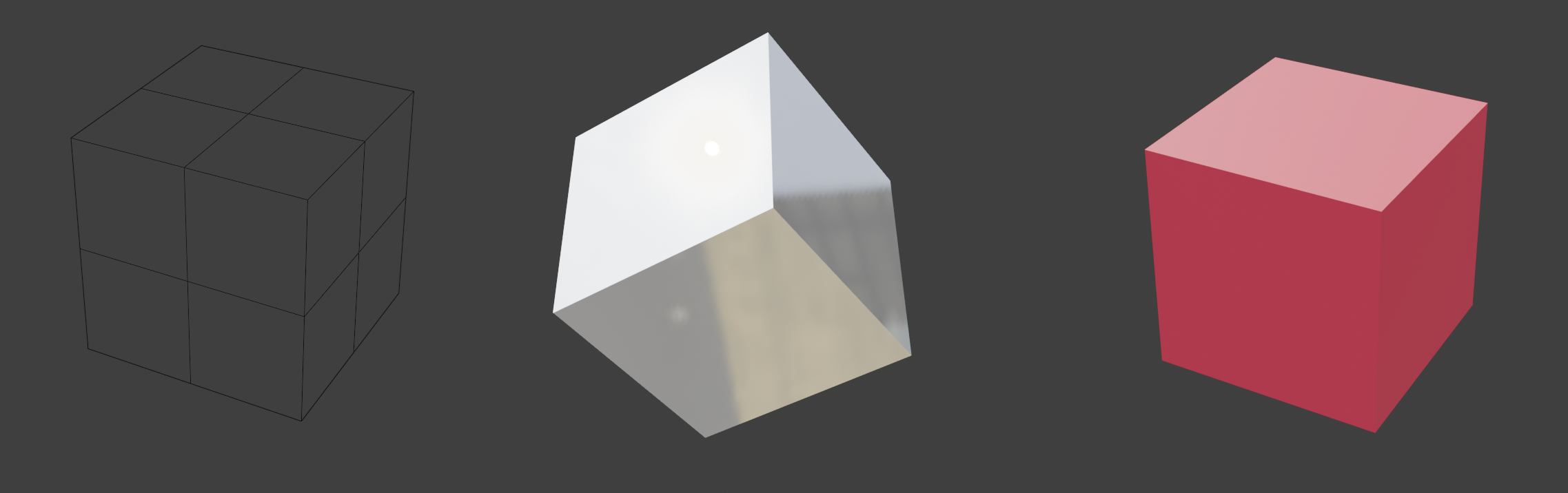
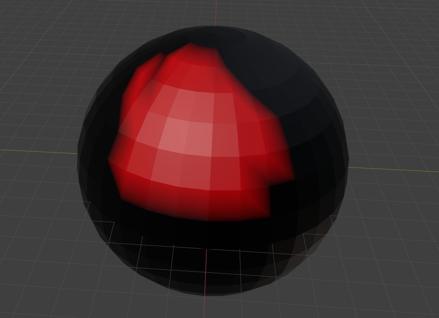
Consider the following (contrived) example: someone wants a model of a mirrored, decorative display case for the 1971 album ‘Push Push’ by Herbie Mann:
There’s between one and four materials here, depending on how you slice it, with differing numbers of textures:
Option 1
Make textures in an external application such as Substance Designer that contain the different properties you need (colour, metallic, roughness etc), then apply those as a single material to your model.
Pros:
- Only one material.
- This is the industry standard way of doing it. If you happen to be a major game studio, you can probably stop reading here.
- Geometry stays extremely simple- four vertices, one face.
- Very flexible from an artist’s perspective. If someone wants a different pattern, you can crank it out quickly.
Cons:
- Three different applications to manage (Unreal, Blender, Substance Designer), each with their own files.
- Lots of textures (colour, normal, roughness, metallic, etc) going into fairly complicated material that combines them. You can reuse the shading code, but you still have to manage all the textures.
- UV editing becomes required, and that can get messy. Well, not for this example, but if this were something more complicated it could turn into a proper trial.
- Substance Designer is £50 a month. Textures can also be made in GIMP or Paint or whatever, but that’s even more time consuming.
Option 2
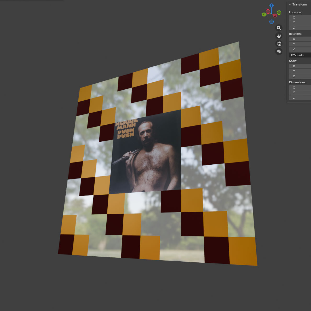
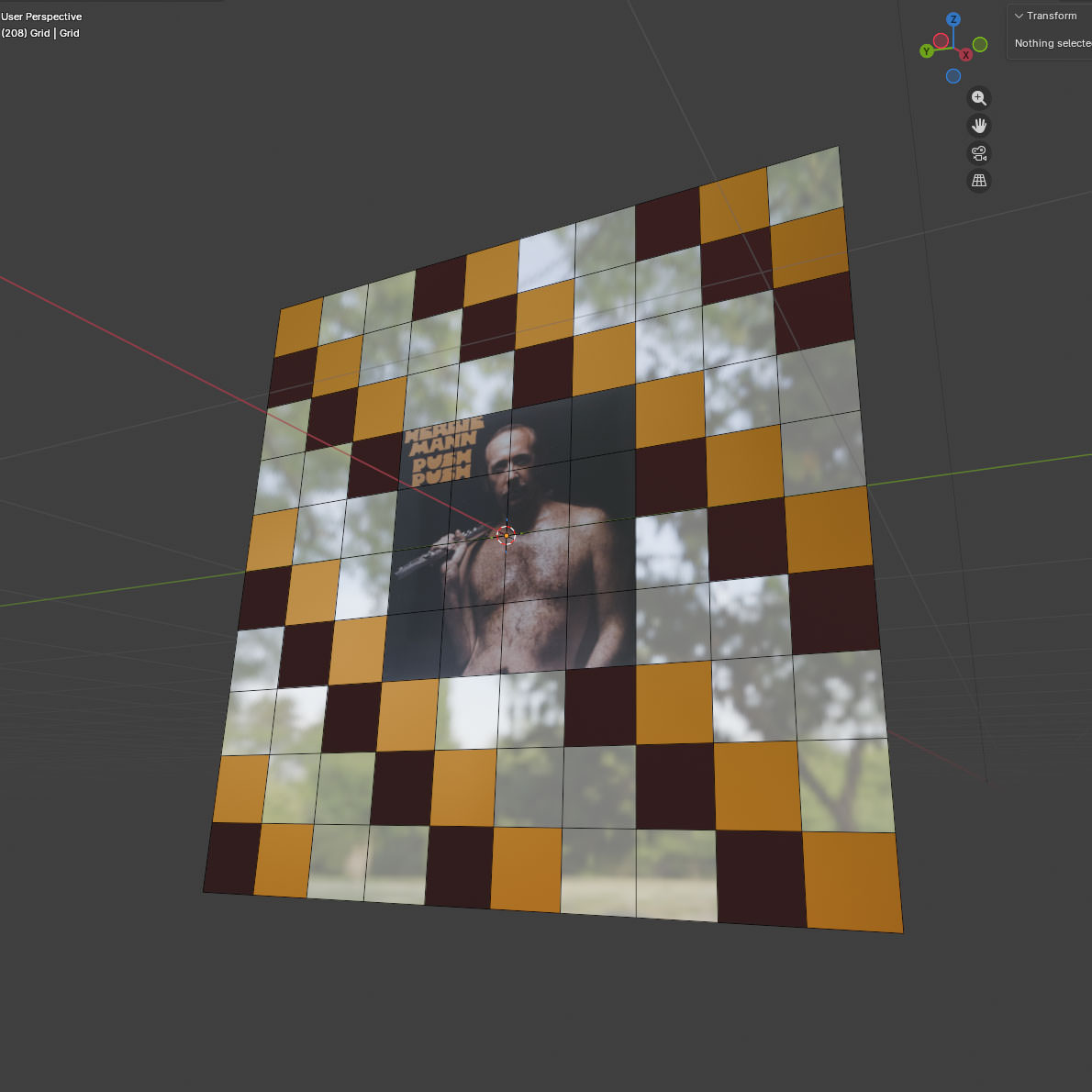
Do the whole thing in Blender- take a grid, carve it up, make the materials, and place them match the pattern.
Pros:
- Actually very quick to do, with instant feedback: everything apart from Herbie is just straight BSDF values, and took about 20 seconds each to make. Herbie’s material took slightly longer, but that’s because I had to plug an extra node in.
- I can stick those materials on as many objects as I like. If I wanted a house covered in Herbie Mann- and who wouldn’t- I could reuse the Mann Material directly.
- There’s still just two applications (Blender, Unreal)
- Only one actual, texture (Herbie himself)- no messing around with different maps.
- Very limited UV editing required. The squares for Herbie required some scaling, everything else is just left as-is.
- I haven’t had to give Adobe any money.
Cons
- Four materials to be exported or recreated.
- The number of vertices in the model has been multiplied by 100. That can be reduced (given the pattern), it’s still a big increase over ‘4’.
- This is not really the standard way of doing things. If anyone else comes on board, expect to spend some time being quizzed over why anyone would do this.
- Big changes to that pattern are going to be time-consuming.
Which of those methods is ‘easier’ depends on your level of artistic ability and the complexity of the model. Sticking a material on a few faces in Blender is pretty trivial, but sticking it on hundreds gets old fast– but if you’re not a natural artist, it’s probably still easier than painting a texture.
There’d be no point to this post if I wasn’t going to explore Option 2 further.
Here’s the thing about Option 2– if you’re prepared to accept some limitations on the look and feel of what you’re building, you can actually save yourself a lot of time by having one or two materials for absolutely everything.
When I first started mucking around with Unreal, I was using a bunch of assets that I’d got as part of some Humble Bundle deal or other, made by a company called Synty
Synty’s assets are all very low-poly, and almost entirely use flat colours. Here’s an example of something from their Polygon City pack:
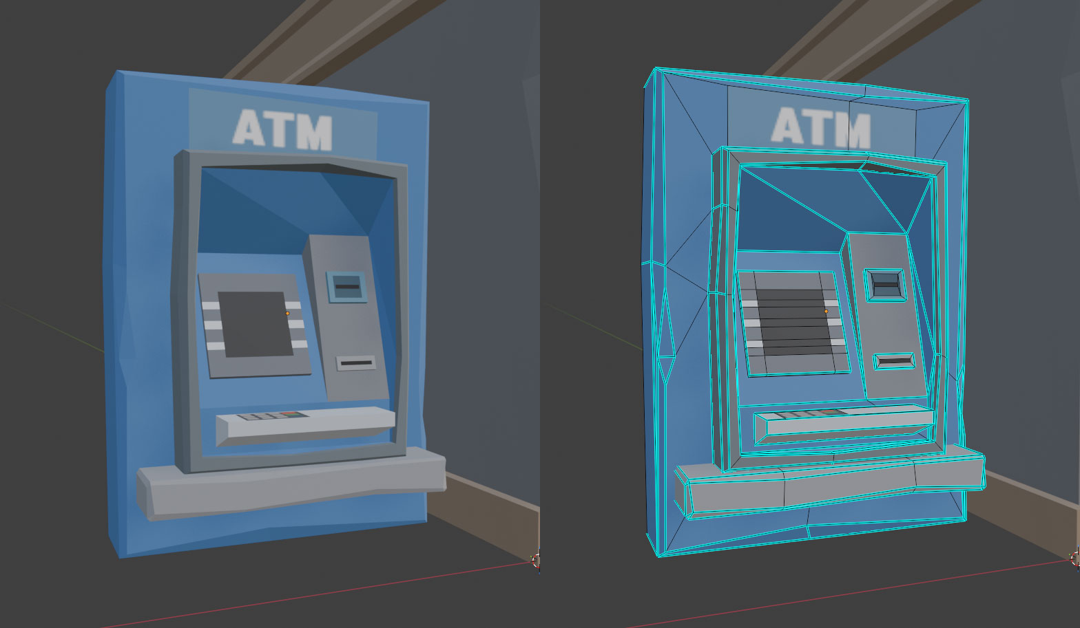
Rather than a complicated UV-unwrapping scheme, most of that model just maps onto a single texture containing colours and a few choice images:
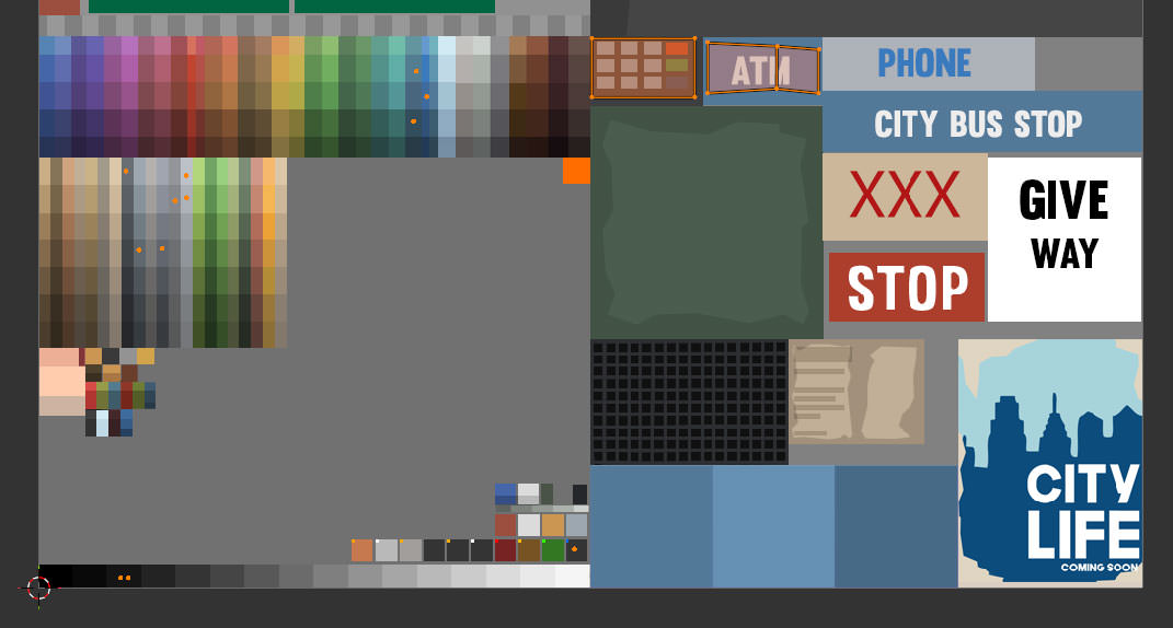
This is quite a neat solution- everything in the pack can use the same material, so the people who made them can just focus on the geometry, and the people using them can focus on building Lowestoft Fly-Tipping Simulator 2027.
UV mapping, if you’re not familiar with it, is a way of mapping the faces of a 3D model to a 2D image. Models can have multiple UV maps, used in different ways. The ATM above, for example, comes with two UV maps- the one above which is used for surface colour, and then a more traditionally ‘unwrapped’ one that looks like this:
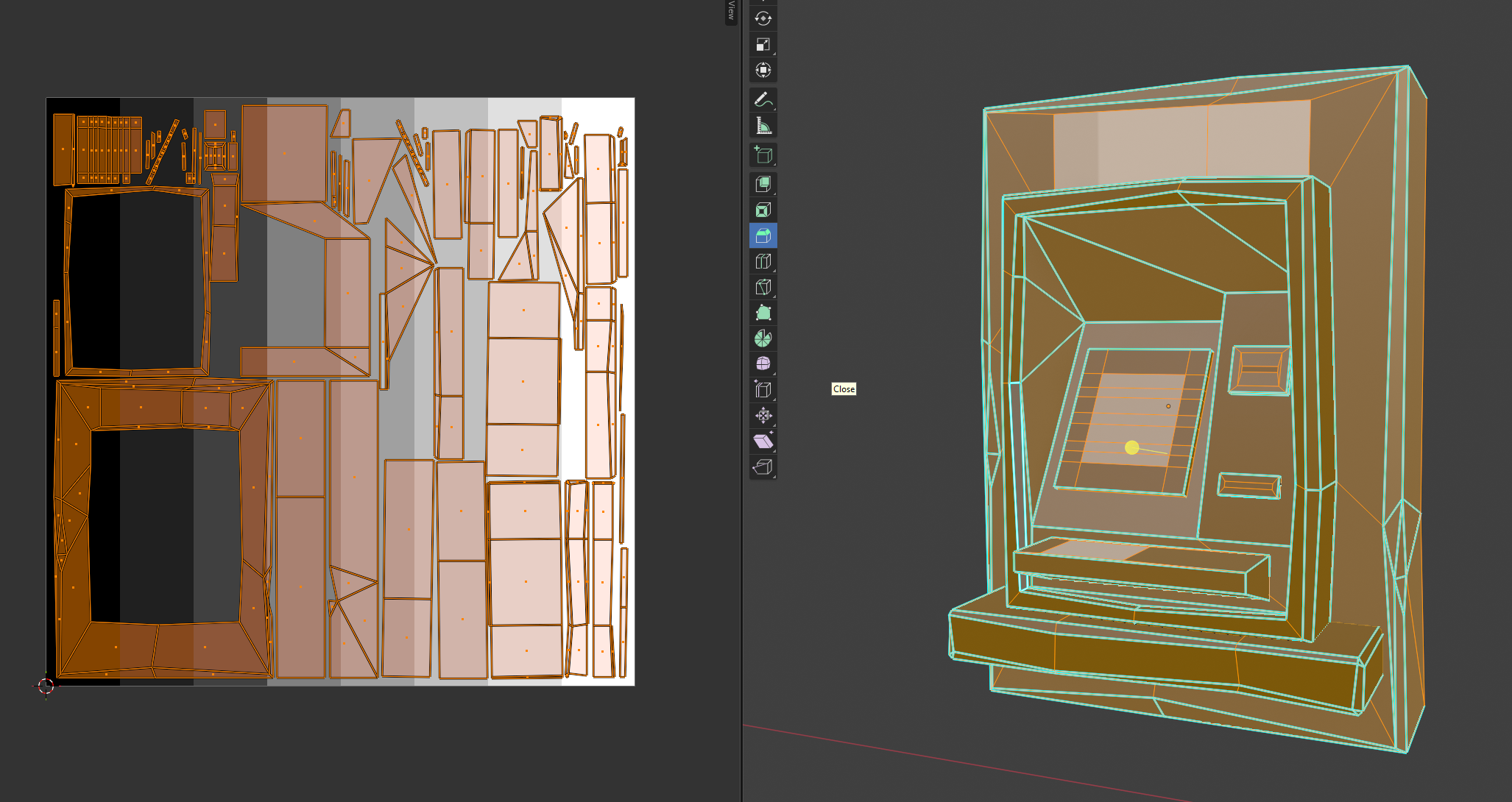
It’s a lot easier to see on the second one which areas of the 2D image correspond to the 3D model, but using that map for colour would require a unique texture to get the same results as using the first. The trade-off here is one between texture reuse, and texture detail. Since the model isn’t particularly detailed, and they only want flat colours, it’s fine to use the first one for colour.
Now I could just use Synty assets, but there are some drawbacks:
- I don’t like the way everything looks like it’s been hit by a sledgehammer.
- They’re very recognisable- once you’ve seen the style, you’ll start seeing it in every indie game that uses them.
- They don’t make everything I need, and even if they did, I’m not going to buy all of it.
- I could just use the textures, but it’s very painful scaling down UVs and dragging them onto the colours compared to clicking on a face in Blender and setting a material.
- They don’t support all the stuff I want to do with materials.
Back in the BSDF
“Let me tell you about bidirectional scattering distribution functions” - the words every woman wants to hear. A bidirectional scattering distribution function, or BSDF (I am not typing that again), is used to model the scattering of light when it hits a surface. Blender and Unreal both use a (the?) ‘Principled BSDF’, parameterised by some values. Changing those values changes what the material looks like, because ‘how something looks’ basically means ‘how light scatters when it hits the surface’. Here’s how they’re set for the Synty models above in Blender:
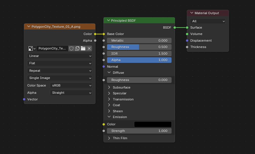
There’s a lot of parameters there, but the main ones I use are colour, roughness, metallic and emission. The others do stuff as well, but if you’re OK not having things like fancy car paint, you can ignore them.
Colouris… the colour.Roughnessis how rough or smooth it is. Think of the difference between stainless and brushed steel.Metallicis, amazingly, if it’s a metal or not. This value is (almost always) either 0 or 1.Emissionis the colour and intensity of any light emitted from the surface.
Synty’s technique is to put colour on one map, lock roughness to some value, ignore metallic and then put emission on a different map referenced by the same set of UVs. They’ve got one particular look, but lots of colours.
I’d like to take it in the other direction– fewer colours, but more options for the other parameters– and also avoid manually having to lay out any of the UV values. The workflow should be: make the model, stick some materials on it, press a button, and have something that I can use directly in Unreal.
So, I did that.
Atlas, My Love Has Come Along
The ‘pressing a button’ bit above means ‘writing a Blender plugin to do most of this’, with the outputs being a ‘Material Atlas’ and copies of our models with the UVs set accordingly. It’s the same idea as a Texture Atlas, but for surface properties.
Here’s the general idea:
- Load a JSON file containing what materials we’ve encoded so far (or create one if we’re doing this for the first time)
- Give the plugin a model, and have it read the materials that are on it
- For each material:
- If the material is in our JSON, move on to the next.
- If it isn’t, extract the properties and append them to our JSON file
- Use the populated JSON to produce an image containing a grid of all our materials, somehow encoded, as a ‘material atlas’.
- Output a new model where the UVs have been placed so they reference the materials on the atlas
The plugin isn’t really the interesting bit– the clever / stupid bit is the encoding itself.
To recap: we’ve got four different values to encode. Those are:
ColourRoughnessMetallicEmission
We’re going to be writing our atlas texture as a transparent PNG, which gives us four channels:
RedGreenBlueAlpha
The first problem is that Colour will take up three of those. I did try using two values for encoding Colour by writing it as HSL and then fixing the value of Saturation to 0.8, but it looked rubbish.
So, I chose to leave Red, Green and Blue for colour. Alpha is mapped to Roughness, as that’s value that varies the most across materials.
Unfortunately, we still have Metallic and Emission left.
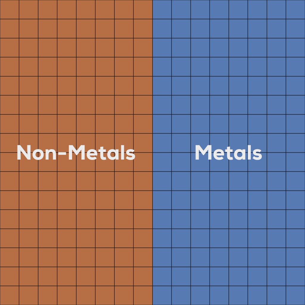
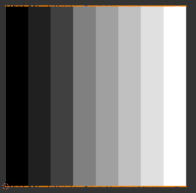
Here’s the thing: Metallic is basically binary– effectively only ever 0 or 1– and binary partitions are easy to handle. So we can put the non-metals on the left and the metals on the right, then in our shader set Metallic as the output of uv.u > 0.5
At this point, we could say that Emission is also binary value and declare ourselves done– things either light up or they don’t, meaning we can do the same as Metallic, but on the other axis.
To compensate for lights being comparatively rare, we could place emissive materials at the very top of our atlas, and then do a check of uv.v > 0.9 in our shader to see if something is emissive. And we can live without the colour of Emission value if we say it’s the same as the other Colour property.
When was the last time you saw a blue thing light up red?
Never.
Done.
Yet while I am no great artist citation needed, even I can see it’d be a shame to lose the information about brightness. You don’t want a scene where all the lights are either blinding or dim.
Fortunately, we’re not just limited to one UV map per model. We can have up to eight in Unreal. That’s great, but there’s a cost to using them- each additional UV map adds size to the model. More size is bad. As such, it’d be a shame to pay that cost just for the sake of one float value.
Still… if we did that, could we use the left-over values to encode… even more stuff?
Enter Geometry Nodes
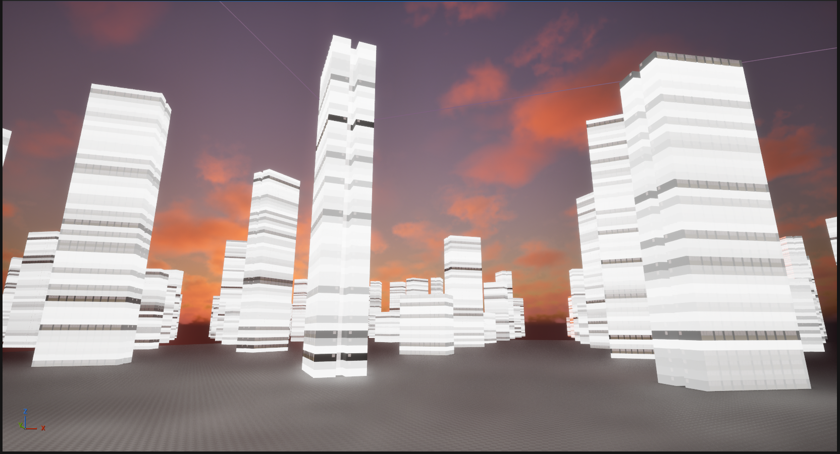
Geometry Nodes is Blender’s programmatic modelling framework. It’s a bit of a headache at first, but it’s also very powerful.
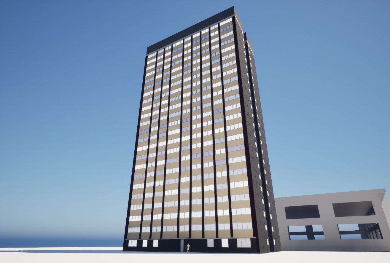
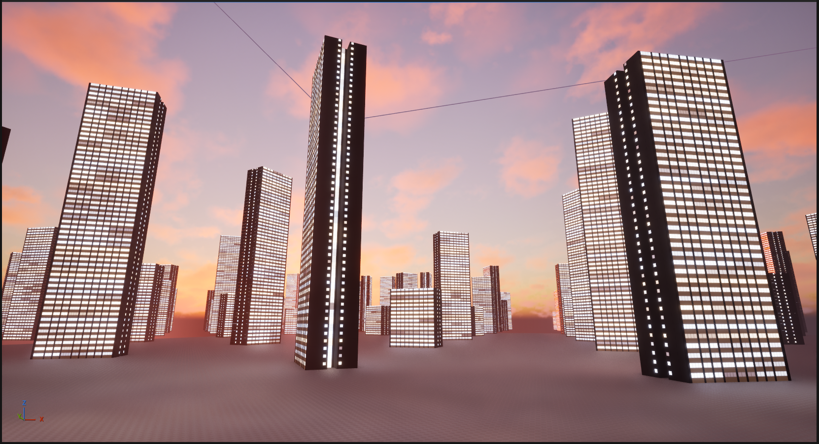
Recall the image at the top of this post. If you’re making a block of flats, you don’t want to have to model every single flat that’s there– you want to model one, and then have the computer copy it to the other locations. Before Geometry Nodes (and to be honest, even now) you’d do that with the ‘Array’ modifier. Changes to the original geometry reflect across all copies at once.
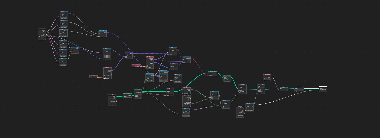
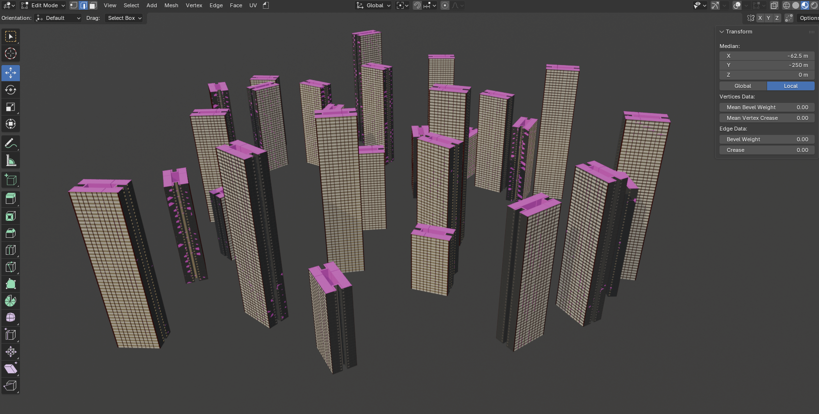
Geometry Nodes is a generalisation of that approach that lets you to build your own modifiers. You can go from this:
…to this:
…without having to place every bloody vertex yourself. That’s great. While you’re doing it, you can read and write attributes onto the geometry to influence later stages. Here I’m writing a random value onto each instance of the original unit:
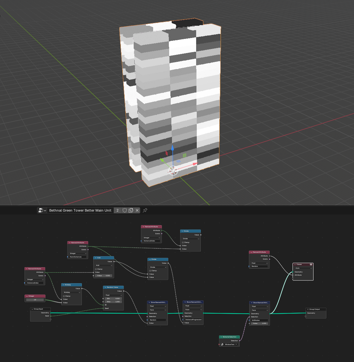
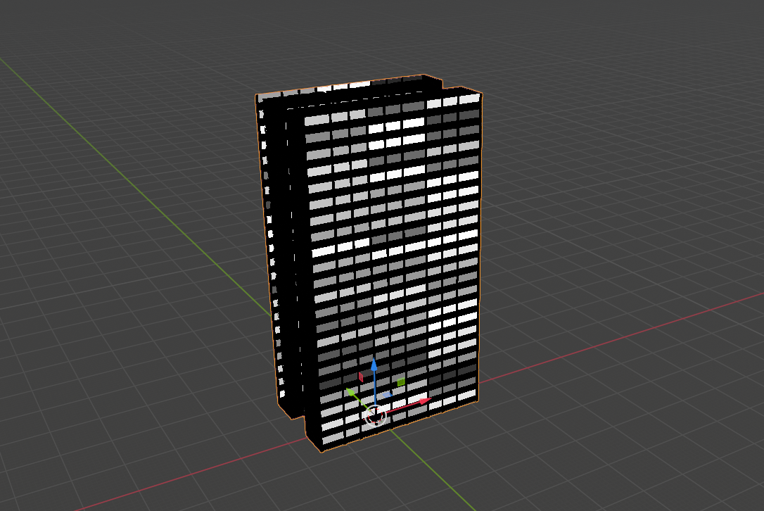
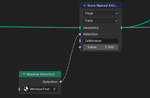
And if I combine that with another attribute saying where the windows are (which is worked out by asking “does this face have the window material”)…
I can make it look like some flats have people in and some don’t when the final material is applied, by referencing those attributes:
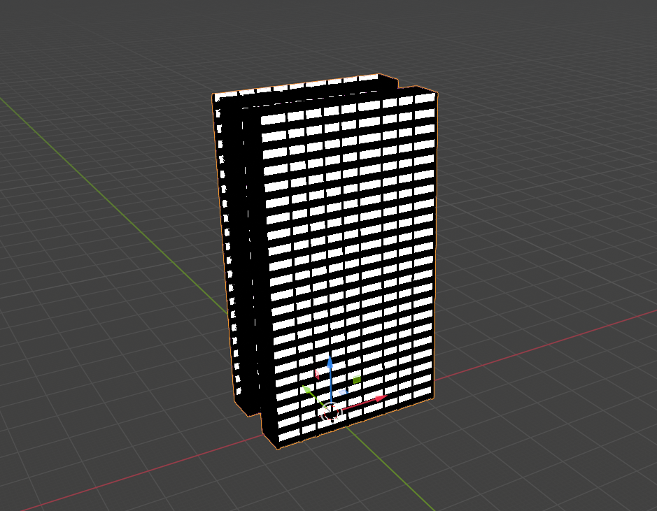
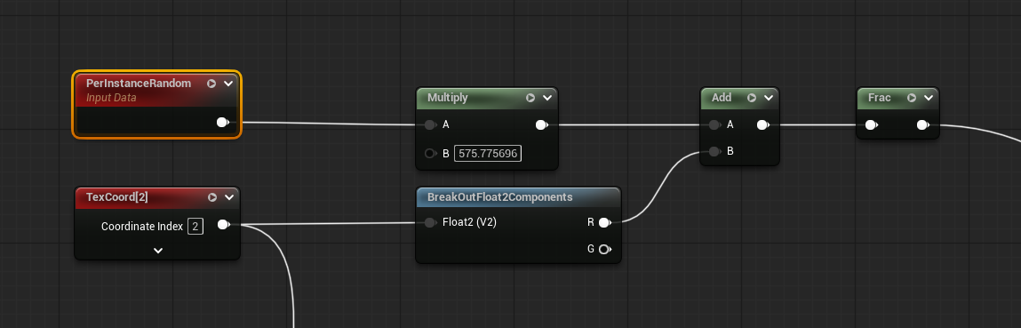
Remember the title of this post? Well, that’s another thing the plugin does- encodes arbitrary data to UV maps. I can take attributes stored on different parts of the geometry and write them to a separate UV map in order to access them in a shader. Here’s what the UV map looks like for the above:
The random values are written along the U axis (or X axis if you’re more used to that) and the ‘Is Window’ flag is written on the V (or Y) axis. When shading this, I don’t even need to do any texture sampling– I’ve got two extra values to write, and there’s exactly two values in the UV map, so I can just check those directly.
If we do a texture lookup, we can use something like this:
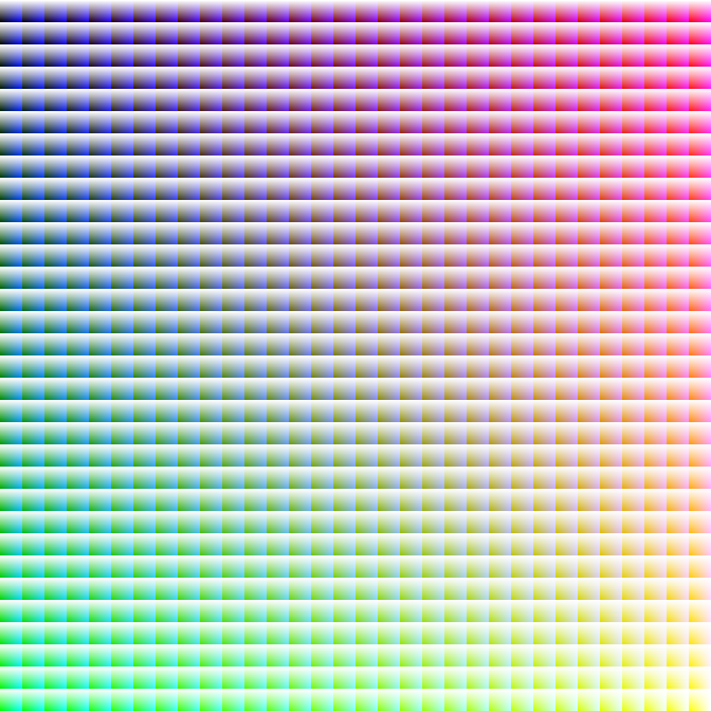
That’s a 32x32 grid of cells. R runs along the X axis of the whole image, G down the Y axis; within each cell, B increases along X, alpha increases along Y. A simple bit of maths to place the UV and you now have four values which can be used to augment shading at the cost of a bit of extra memory per model, and I’m still only using one shader. And I’ve still got more UV maps I can use if I want to be even more perverse!
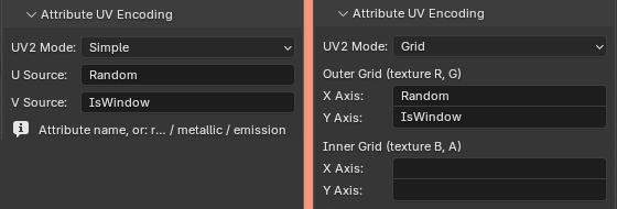
The plugin has options for both of these encodings: ‘simple’ encodes two values, and ‘grid’ encodes four. Enter the names of attributes that you want to pick up and they’ll be encoded to the second UV slot.
There’s a few extensions possible here. It’s currently locked to just outputting one UV map for surface properties in the UV1 slot, and attributes on the UV2 slot, but as noted before, we could add more UV maps if we wanted to.
Another possible extension comes from noting that UVs are written as standard floating point values, so they don’t have to stay in the 0 – 1 range. [9000, -69.67] and [3.142, 1.1618] are just as valid as [0.1, 0.1]. You can either use that to make the code easier to read by checking against integer values, or– if you’re feeling really spicy– encode one value as the integer component, and another value on the fractional component.
For example, say you have one value which is 5, and another which is 0.358. If you set the uv.u to 5.358, the first value can be retrieved in your shader with floor(uv.u), and the second value can be retrieved with fract(uv.u). The second value could even still be used as a regular UV coordinate to look up a different set of four values in the fancy rainbow map above.
What could possibly go wrong?
Obviously there’s drawbacks here:
This atlas limits me to an NxN grid of materials, which with current settings limits me to “just” 256 metallic and 256 non-metallic materials. If for some reason I decide that’s too few, or that I want to adjust the ratio of non-metallic to metallic, I’ll need to re-process all the models I’ve made or the materials will be wrong. And that will be shit.
It’s not particularly collaboration-friendly. If there were
anotheran artist working using this at the same time on the same project, we’d need to keep things in sync. Storing definitions in the JSON mitigates that somewhat; that could also be changed to a folder of JSON files to make it more amenable to git.Names and definitions need to be consistent for the Blender materials across files, as that’s what the atlas is indexing on. That probably means keeping them in a single Blender file and then linking data to new files. Again, not super-collaboration friendly, and possibly prone to screw up.
Additional UV maps make models bigger. Right now I’m using one “standard” one, unwrapped the regular way (more on that shortly); one for the material atlas; and one for the additional ‘is window’ ‘random value’ pair. An additional one is also required for the lightmap, which Unreal generates automatically.
Not a major issue, but if I want to apply one of the materials in the atlas to something that hasn’t gone through this pipeline, I’ll need an extra material in Unreal that has some parameters I can change to use as a pseudo-UV coordinate.
Nothing’s locking me into this for models that don’t need it though, so I can just say “this is for all unimportant static meshes” and then use the ‘proper’ method for anything that needs it.
Some other things the plugin does
Before we get to the big payoff, a quick aside on some other pain points I decided to kill while I was at it. This plugin doesn’t just work on single meshes– it can do whole collections, and then merge the output. There’s also some options for the more common clean-up operations, like merging duplicate vertices.
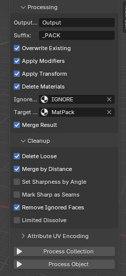
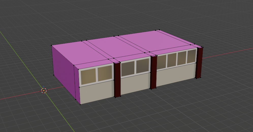
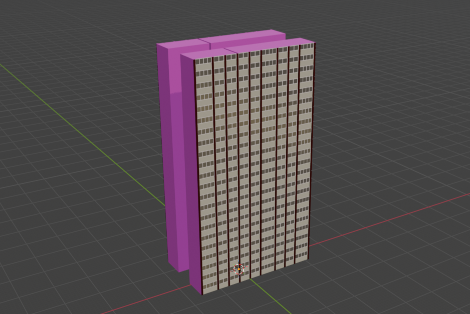
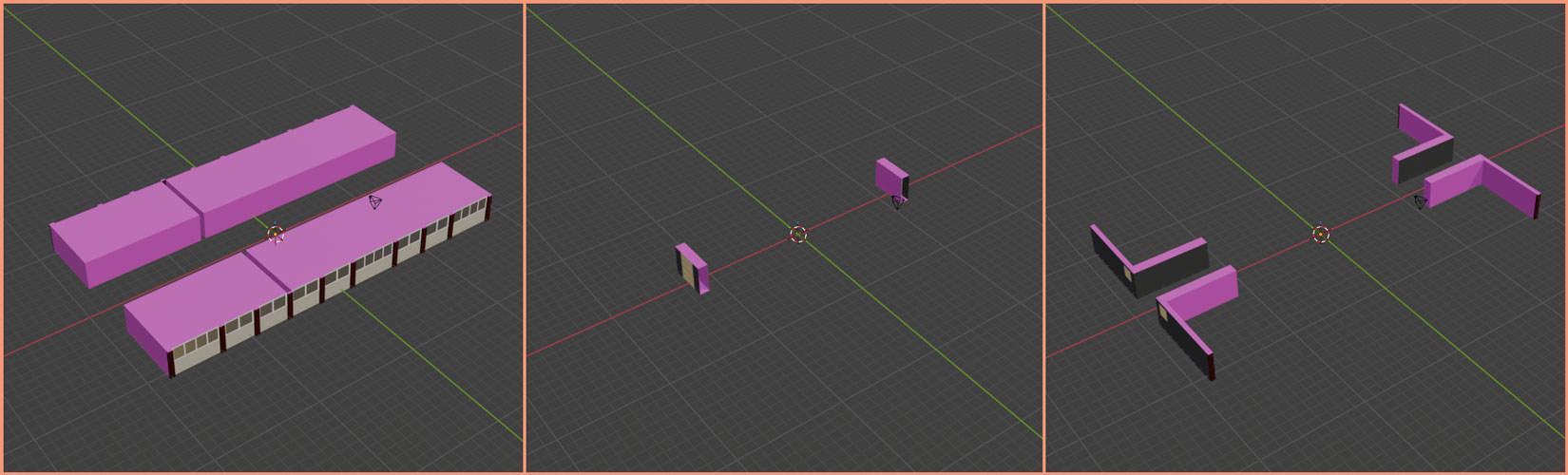
I can also specify a material which, when applied, will cause any face that has it to be deleted from the output. Since I’m usually building parts, running them through Geometry Nodes, and then combining them, I can wind up with a load of internal geometry that isn’t visible from any angle. If it’s not removed it means the models take up extra memory, which is bad.
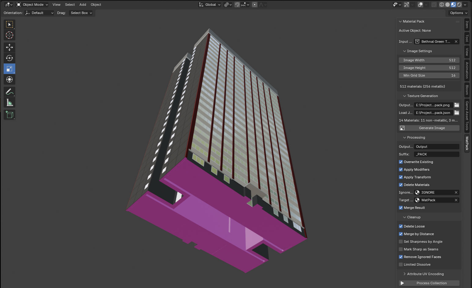
The pink material is the one that’s going to be removed. When processed, that gives us this, which is nicely hollow-
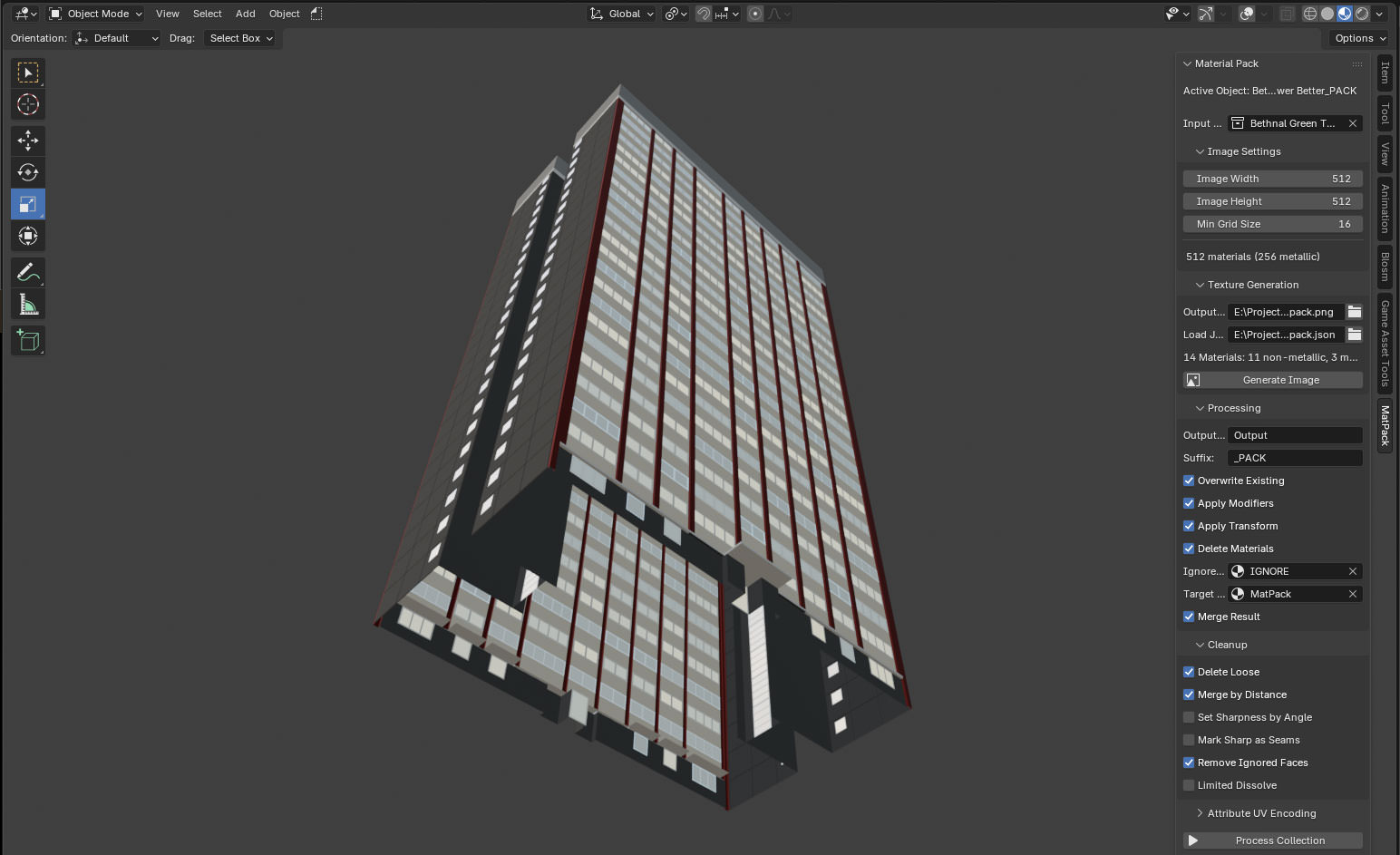
Now, I could just build everything as flat faces, but whilst modelling, it’s significantly nicer using solids. Being able to flag something for removal and then have it just gone after processing is very useful.
PCG Angle Dust
If you’re name is Tim (hi Tim) you’re probably wondering if it would make more sense to ditch the Geometry Nodes part entirely and do all this in PCG.
Well, I could, but some things are easier in Blender, and some things are easier in Unreal… and it doesn’t need to be one or the other! This whole thing gets significantly better if you use it with PCG. So let’s dig into that.
Let’s say we want a whole load of buildings that look like this, but have different numbers of floors. For that, we’d need to take a single floor and duplicate it upwards a random number of times (and then maybe put the roof at the top as well, but let’s leave that for the time being). If we do that straight in Blender with Geometry Nodes we’d get something like this:
Doing the same thing in UE5 PCG is pretty straightforward–
If we then use the ‘per-instance random’ node in the Unreal material, we can set the brightness of the lights. But we’ve exported the whole floor, so the brightness will be the same across all of it. And we still have the problem of flagging which bits are windows and which bits aren’t. Walls don’t typically glow.
If we wanted variance within the floor, we could drop Geometry Nodes entirely and use PCG to put the building together… but this building has a slightly annoying footprint that wouldn’t be portable to many others. Each floor is made of three different parts, duplicated in Geometry Nodes in three different ways:
Creating a PCG graph to put all the bits together of this wouldn’t be a great idea- you can’t use it for anything else, so it’d be better to export a whole floor. This was a problem I encountered when making the Infinite Barbican Centre - but I was on a deadline, so just did it all in PCG anyway.
However– with the UV attribute encoding, we can add a random value to each part of the floor that corresponds to a single apartment, combine that with the per-instance random value in the shader, and then use that as the lighting value.
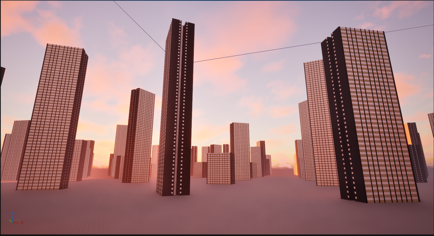
And we have the ‘Is Window’ attribute encoded as well, so we can mask the non-emissive bits. There might still be a bit of repetition, but it’ll be far harder to see. If we also use the per-instance random value to set the colour temperature of the light…
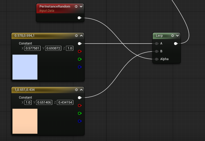
…we get a rather nice result.
By encoding the semantic data, we get to use Blender for the bits that Blender is best at, and UE5 for the bits that UE5 is best at, whilst keeping everything pretty re-usable for other models. Any building could use that PCG graph; any model with the encoding can use that shader. There’s also only one texture to re-import when we’ve added more materials, and we’re only adding the materials in Blender, not in both Blender and Unreal.
There’s some limitations to the look, but personally I don’t mind them- and, importantly, in terms of quick iteration, it’s a big win.
So what about vertex colours?
What about vertex colours?
As the name suggests, vertex colours put… colours… on… the… vertices. You can use those colour values to store non-colour data in the same way as above. The difference is, they go on the vertices, rather than the faces. Blender allows you to paint them as a ‘face corner’ attribute, which makes them the same as UV maps, but I have no idea if UE5 can read them back in that way. Also, from what I can tell, UE5 only supports a single set of vertex colours per mesh.
Is this better? Well, it depends on what you’re doing, and for some things it might be essential. UE5s ‘World Position Offset’ is the only thing that comes to mind right now, as that needs to be done in the vertex shader. The vertex shader doesn’t have access to UVs; UVs are a property of faces, not vertices, and can only be accessed in the fragment shader stage.
‘Vertex painting’ to set vertex colours is also widely supported in a number of applications (including both Blender and UE5), whereas ‘face painting’ isn’t, at least not in this domain.

Bonus: Windows ‘26
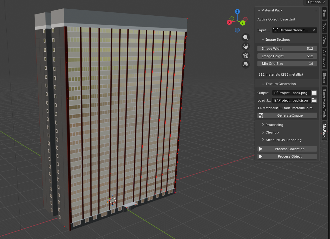
Just to demonstrate that I have used this for more than one model, here’s another block, this time based on the ones around the shopping centre at Surrey Quays:
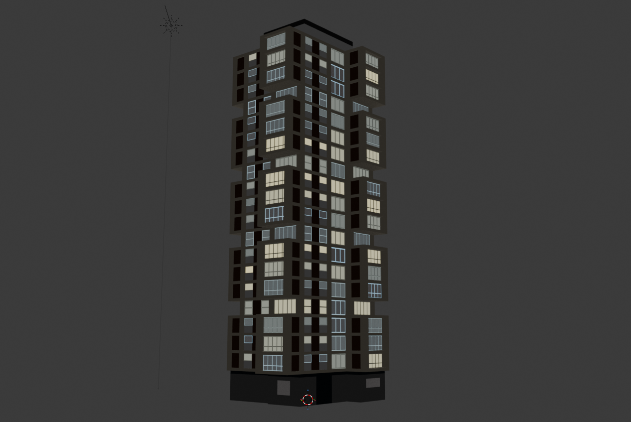
This processed version is using exactly the same material as the one from Bethnal Green above, despite having different input materials, so the method does work.
Whilst I was modelling this one, it became apparent that I’d need a lot of windows, and I didn’t want to have to cut geometry for all of them. And so, another plugin! This one takes sets of faces and tweaks the UVs in the first map (i.e. the one that is being used properly for texturing, rather than to encode BSDF properties or other data), so that they appear to have a window frame repeating over them.
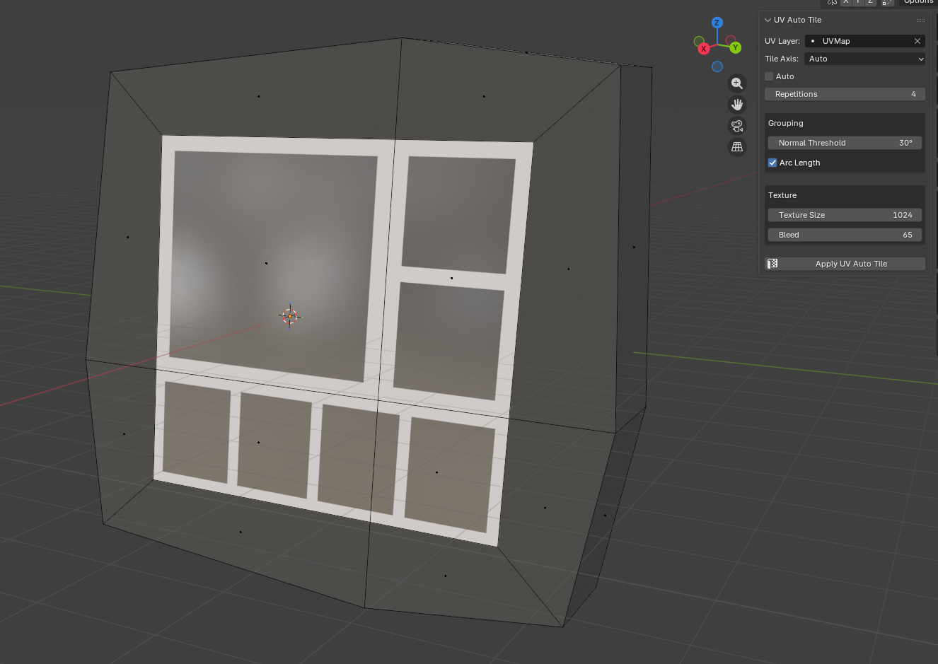
The texture for that is just a square box with a transparent centre. I set the number of repetitions, it repeats the UVs in the axis I want, and it gives the impression of multiple window panes. I then assign a ‘window’ material to those, which is what gets checked in Geometry Nodes to determine the value of the ‘is window’ attribute to be written out:
It does make this set-up a bit more specific to rendering buildings, but there’s almost certainly a way (I’m thinking 2D texture array) to generalise this for other objects. Plus, a lot of objects won’t need the extra encoded data, just the surface properties, so it all still works.
Anyway, that’s where it is now. I’m going to extend it to also do aspect-correct UV projection so I can use it for signs because for some reason that’s needlessly difficult in Blender.
Fin
I doubt I’m the first person to have thought of this, so if you’ve got any other ideas I’d love to know. There’s potential here for lots of other things– flagging which parts of a model should have a random colour, for example.
At some point I’ll stick the code for this on GitHub, as I’m not super-precious about it, and either way, after I’d figured out how I wanted to do this, all the boring UI stuff was done by Claude Code (!).
“But Ed, you hate AI”
I hate AI “art”, I hate AI music, and I really hate AI writing. I will never let an AI write or say anything for me, because that’s surrendering too much.
I have changed my mind about AI coding because so much of coding is busywork– lining up values with functions, working out which part of an API you’ve never seen before you need to call to make a button change colour, writing six versions of the same function so it works on different data types, and so on.
After seeing AI agents used for coding properly, I think it’d be daft not to use it– but the key word there is properly.
I have another blog post planned this, but in short: if you know how to solve the problem already, and could in principle write it yourself, Claude Code saves you days. You can tell it exactly what you want and it will do it, and provided you’re checking the output – and you really do have to do that – you can keep it on a tight leash when it goes off track.
If you don’t know what you’re doing or what you want before you ask Claude to build it, you have a 50% - 80% chance of winding up with vibe-coded garbage.
Still, that’s for a future post, assuming the singularity doesn’t occur while I’m painfully typing it out.
===
Special thanks to Tim (creator of the incredible PCGEx) for the technical feedback on this piece, and Kayleigh for the nitpicking over syntax